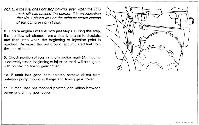
The engine has been difficult to start after the rebuild (same situation as before the rebuild), and was particularly difficult after the engine had been running for a while. Sometimes it had to set a spell before it decided to start again. I figured the best place to focus on first was injector pump timing. This timing evolution is sometimes called a "spill test". The instructions say to undo the injector lines at the pump, then pull out a "delivery valve" on injector pump #1 outlet, then install a suitable piece of tubing on top of the outlet. At certain points of crankshaft rotation, fuel will flow freely out of the tube since the delivery valve is removed, then at some point of crank rotation the flow will stop. This point is called "beginning of injection". That point should put a timing mark on the crankshaft pulley in line with the timing pointer.
My timing was a bit retarded, so I took out one of the two shims under the injector pump. I tried starting the engine but no go. I should mention here that when I was messing around the injector pump area, I decided to adjust something called a "torque screw/spring" that interacted with the governor. Ok, back to the engine not starting. I messed with things for probably an hour, removing and installing the injector pump multiple times while adding and removing shims under the pump, but the engine just wouldn't start. Well, it would give a lone pop every so often and then die. I finally wondered if the governor/torque screw adjustment had anything to do with this issue. I undid the adjustment I'd made on the torque screw and the engine then started. Hmm. I followed the torque screw adjusting procedure to the tee. Not sure what went wrong. So I then just adjusted the torque screw to a point that seemed to work well.
I then turned my attention to getting the dash back together. It has been laying loose on the cowling due to wiring issues since I first got the tractor. I'd ordered some sheet metal u-clips to attach the funky dash. I say funky because it's just a piece of sheet metal that someone at some point in the past replaced the original plastic molded dash. I think the original dash was screwed to the cowl from the bottom, and whoever put this sheet metal dash in used bolts which were a pain and a half to get out when I'd pulled the dash apart for the wiring. This first photo below shows a couple of the u-clips installed, then the next photo shows the dash screwed down properly. Even if the u-clips aren't what was used originally, I like them because I can take the dash off fairly easily, which is almost a regular occurrence with this old tractor.
With the tractor running well, I tried using it to load our trailer with yard waste. I got five scoops dumped in the trailer when the tractor died. And it wouldn't start. I finished loading the trailer with the other tractor. The next day I worked on this tractor. First order of business was to bleed the injector lines and pump, just in case that was the issue. After bleeding, the engine started and ran for maybe 30 seconds, then died again. So I tried bleeding the injector lines again. A milky white substance came out. Great, there's water in the system. So I drained the fuel tank (something I should have checked when I first brought the tractor home) and about 1/2 cup of water came out. I refilled the tank and flushed the lines.
Since I was using the battery so much with the water issue, I put a charger on the battery, at which time I found out the alternator wasn't charging as it should, so I got out the wiring diagram and started checking out the connector wires at the regulator. I found the ground wire had high resistance and at that point something in the back of my brain clicked on. I'd seen a wire under the tractor where the headlight harness poked out at the front of the tractor and this wire wasn't connected to anything. I thought at the time the wire was for the lights, which are at the moment non-existent, so I didn't do anything with the wire. Well, it happens to be the ground for the regulator. Never mind that the terminal is three feet from the regulator. So now the alternator is working again, first time since the engine rebuild.
One thing I failed to realize is that there are some interlock balls that prevent the movement of two shift fork rods at the same time, thereby preventing engagement of two gears at once, which would lock up the transmission. I should have realized that fact but I didn't. I put the tractor mess together and when I was done, I had one little ball bearing left over that I didn't know where it went. I should have had two, but one got lost before I got the tractor. Below is a picture out of the manual that I recently acquired showing one interlock ball and where it goes. One ball goes between the right and middle rods and the other one goes between the middle and left rods.
To install the two interlock balls at this point, I'd need to drain the transmission fluid, then split the tractor apart like it had been when I bought it. I have been carefully shifting the tractor with no issues up to this point but I figured if anyone else is going to drive this tractor, I need a fail-safe means to not get the tractor in two gears at once. Not desiring to split the tractor, I decided to make a shift gate. Below is a mockup of it in cardboard. For those who know these tractors, there is a boo-boo in my mockup that I'll explain further down.
Once I got the slots where I thought they needed to go on the cardboard, I transferred the measurements to a piece of steel. I then used the mill to cut the slots, shown in the next several photos.
Ok, here comes the boo-boo repair. I should have realized that there shouldn't have been a slot where I have the piece of steel clamped in to be welded (photo below). It's a 4-speed transmission plus reverse, so there should be five slots, not six. The red metal piece is upside down in the photo but if you can imagine, 1st/Rev is the left slot, 2nd/3rd is the middle slot, and 4th gear slot is the short one on the right. *sigh*
This next photo below shows the shift gate installed. This may be the only JD 650 with a gated shifter. It's kind of a throw-back to my JD 440, which had a gated shifter (although it was a 5-speed, so it had six slots). Come to think of it, my JD B's also had gated shifters.
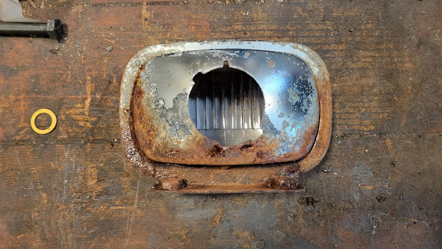
Below are a couple photos of the tractor as it sits now. It's been a long (but satisfying) process up to this point. I have some headlight sockets coming in a few days, so maybe I'll tackle the lighting/wiring rats nest then. They are hopefully the right size to fit my headlight housings. The parts manual I have for this tractor only lists a complete headlight assembly, and these sockets that are coming are for what appears to be a garden size tractor. We'll see.
The printing on the shift knobs is getting quite worn, so I put on some labels.
It is a few days later, and I got the headlight sockets in the mail yesterday. They're the wrong size, but I will make them work with some Gorilla Tape. Sure, why not.
I made a new wire harness for the lights that would join with the harness running along the frame to the base of the grill.
The headlights look yellow in the photo but they are whiter in real life. They're not blinding but should help in the dark.
I bought this tractor for $2,800 and put $900 into it in parts so far, for a grand total of $3,700. I may have overpaid but I still like the tractor very much. That is, until the next thing breaks.


No comments:
Post a Comment