Ah yes, brakes. One of those systems on an old vehicle that usually needs a lot of work. And this truck's brake system falls into that "usually" category. I figured I'd try the easy three-step fix first. You know, the Dead Dodge Garage (youtube) method.
Step 1 - see if brake pedal goes to the floor
Step 2 - fill the master cylinder with brake fluid
Step 3 - pump the brake pedal until something changes - hopefully the pedal starts to get firm
With this plan in mind, I'll dive right in. The first order of business is to get access to the master cylinder (MC). On virtually all modern vehicles, it's under the hood and in easy reach to allow for servicing. This truck? Nope. It's under an access panel in the cab floor. Fortunately the panel was held in with just "a few" bolts. Eight to be precise...


Below is a slightly better shot of it.

I tried loosening the pipe plug cap with a 12-inch adjustable wrench but the cap wouldn't budge, so I tried a little heat, which did the trick.


That was not an easy process to get the MC out. Even though this is a truck, and an old, simple one at that, everything I seem to touch to fix is difficult to reach. Yes, that includes the MC. After about half an hour, it is out and on the bench. Notice in the photo below the "DPCD" cast in the MC to the left of the number. That means this is an original Dodge/Plymouth/Chrysler/DeSoto part. I don't know if it's original to the truck but it is genuine Dodge.

Here's a little better look at that DPCD.


Ok, it's several days later and I have decided to try and sleeve this MC myself. I have the equipment in the basement, so why not give it a try, right? Yeah, things can go south very easily when boring out an original Dodge MC. I'm willing to take the risk though. We shall see in several days if I made the wrong choice. I can always still just buy a new MC but I've already ordered a kit to put new guts into this one when or if it gets fixed.
I did buy a new tool to do this job. It's an adjustable boring head. It was $66 from Amazon. I bought the one that has an R8 shank, as my mill is that size. The mill unfortunately doesn't have the range needed to bore a 6 inch long bore, so I'll be using the lathe. It requires a bit more fixturing to hold the master cylinder rigidly in place. The photo below shows the 90 degree plate I'll bore a hole through to hold the MC.


The long boring bar came in, so we're off to the races with this part of the job.

The boring is complete and there is some chatter but it isn't going to be a sealing surface so it will be fine.

The new bore measures 1.356" so I need to find some 1-1/2" bar stock.

Fortunately I happened to have a chunk.

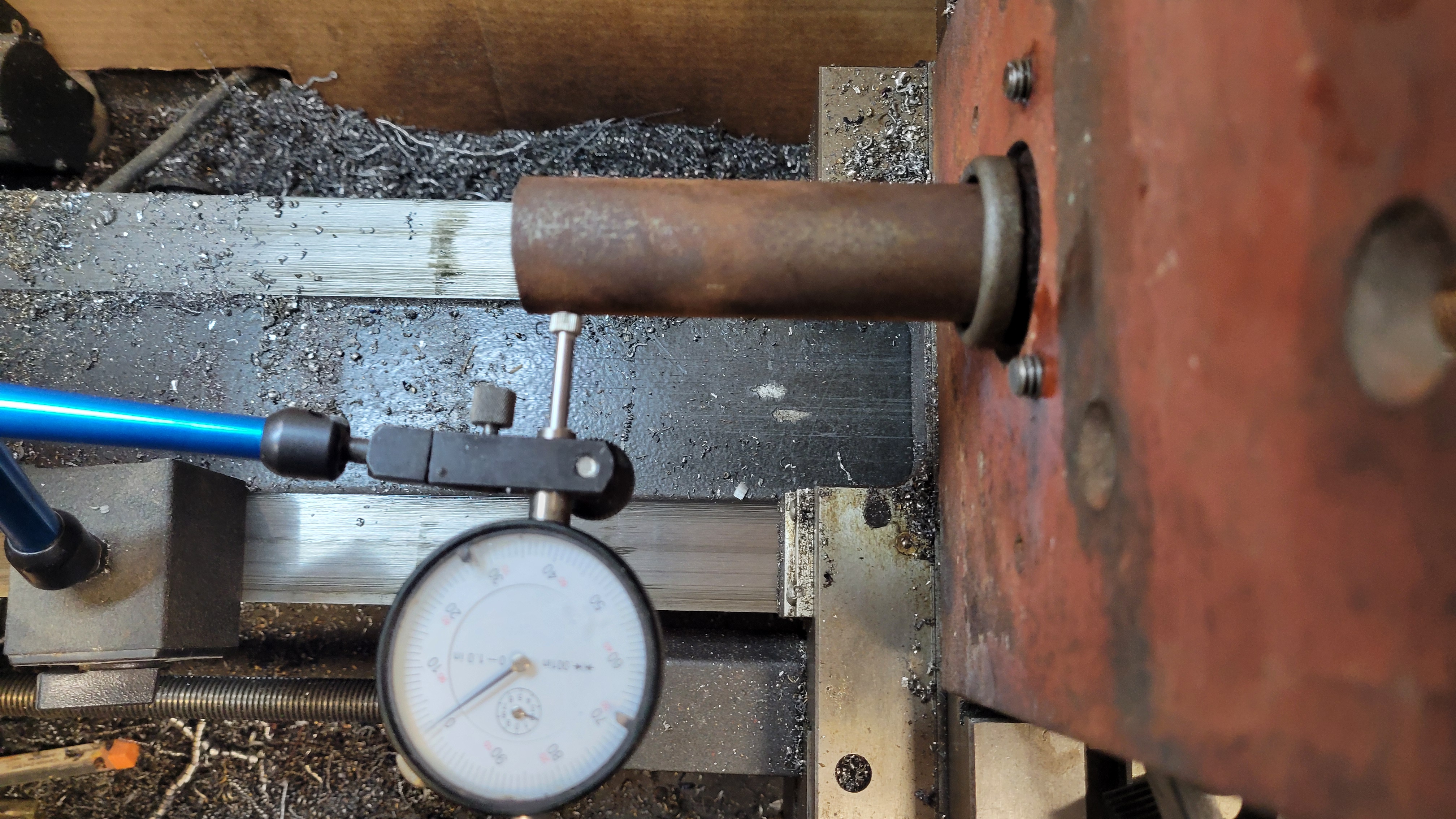
Below is the outer diameter turned down to about 1.355" so it will be a tight slip fit into the MC bore. This photo shows me using a cutoff tool to cut the bar to length.

Next is to drill and bore out the center of the bar.


I had to bore from both ends, as there was too much flex in the boring bar to do an adequate job from just one end of the sleeve. There was a slight mismatch in the center of the sleeve due to boring from each end, so I used a brake cylinder hone to smooth the transition. I think it will be fine....

Here's a test fit of the old plunger in the sleeve. It fits nicely.


It's a 7 month gap between the above and below photos, as I got a couple "new" tractors in the collection that I "needed to" tinker with. I know, I have too many projects. Anyway, the below photo shows some JB Weld applied to the outside of the new sleeve.


I decided the MC needed some paint protection.


I got everything reinstalled and the brakes bled, then took the beast out for pretty much its maiden voyage since I bought it. Previously I had driven it on the road outside the house for a few hundred feet but for the maiden voyage I took it around the block and got it into all four gears. The brakes worked but something is definitely out of adjustment, as I had to stand on the brake pedal to get the thing to stop..... eventually.
The main reason for the push to get the brakes "operational" (using the word lightly) was to drive the truck seven miles to the tractor show my club was putting on over the weekend. I got the brakes done on May 2 and the show was May 7 and 8.
The truck did make the trip both to and from the show without incident, although the brakes made the drive the most harrowing experience I think I've had in a vehicle. My wife drove behind me both ways, as the beast has no turn signals or brake lights. I did use hand signals so I had that going for me...
This photo below shows the WC51 at the show, it's on the far right.


Here's a better photo of the BN at the show that someone else took. The fellow who took this photo owns the Farmall 300 next to the BN. His tractor is nice. He paid $2000 for it, which seems like a very good price.

Update 6/14/2025: I was under the truck today and noticed this:

Yes, that's brake fluid. It's coming from the left rear brake cylinder. I really didn't want to have to mess with the brake cylinders at this point in time, but I can't really drive the truck with this issue.
Here's a little side tangent. I thought I'd put together a sketch of how the brake adjustments work on this truck. It is a bit different than normal drum brakes. The brake shoes are the black/red things, the brake drum is blue, the wheel cylinder is orange, and the adjusters are the yellow and green dots. The yellow dots are actually eccentrics that move the shoes slightly up/down and in/out when they are turned. The green dots move the shoes in/out when turned.
The left sketch below shows properly adjusted shoes that are centered inside the drum, and when the brake cylinder pushes the tops of the shoes out, all of the friction material contacts the drum. The right sketch shows the shoes up too high, and when the brake cylinder pushes the tops of the shoes out, only the tops of the friction material contacts the drum. I initially thought my brakes were all adjusted too high when I bought the truck, and the brakes were practically useless. Later on I realized it was the wheel cylinder pistons that were stuck. See a future blog posting on that job.

No comments:
Post a Comment