I really should work on something like the Farmall C that needs a lot more help than this truck does. I actually did move the Farmall off the lawn and into the garage today though (I'm sure to the delight of my wife), so it will be easier to work on it. I got a couple large bearings for the front pedestal so I might have enough parts to get the front wheel assembly put together and mounted on the tractor. That will make it so much easier to move it around in the shop. But enough of that, back to the truck.
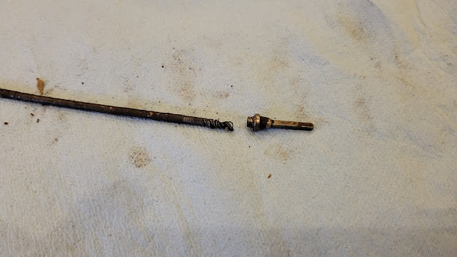
The speedometer cable had been disconnected from the speedometer when I got this truck. I took a look at the end of the cable and the square drive piece was missing, like it had been twisted off. I felt up behind the dash and found the stub still in the speedometer. I tried to turn the spinny part of the speedometer (not sure what else to call it, the part that is driven by the cable) but it wouldn't budge, which is precisely why the square drive had been twisted off. I pulled the speedometer out of the dash and decided to delve into it. Without too much difficulty, I got the spinny part of the speedometer to turn so I chucked up the stub of square shaft from the cable into a drill motor and started things spinning. The speedometer worked but the odometer and trip meter did not.
Side note, this speedometer was made by the Moto-Meter company in La Crosse, Wis.
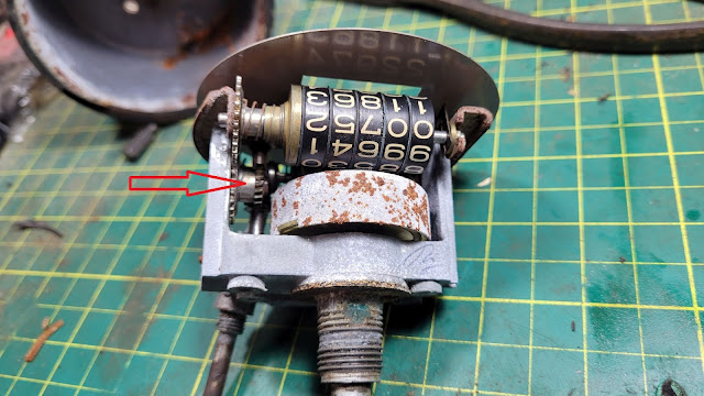
This next photo shows the reset shaft pushed in and its cone (red thing) engaging a cone (green thing) on the trip meter gear. The trip meter gear is spring loaded and shifts to the left (red arrow) when the cones engage, which disengages the drive gears so the trip wheels can be rotated freely. This is a complication that almost seems unnecessary on a rudimentary 80-year-old military vehicle, but I'm sure it would have come in handy for the guys driving these things during the war to be able to start a trip from zero.
Now that the speedometer is nearly all back together, I need to focus on the trip meter button, and how I'm going to keep it on its tapered shaft. I decided to drill a 1/16" hole through the button and shaft, then I can drive a brass pin through the hole.
I made the pin slightly larger than 1/16" so it would be a press fit.
That should work.
With the reset button issue fixed, the next step was to carefully hammer the bezel crimp all the way around the housing. I went around a number of times bending the lip slightly more each time so as not to mess anything up.
And now for the final product. I applied a coat of paint to the outside of the housing. There is a bit of paint on the glass I'll clean up when the paint dries.
I pulled the innards out of the speedometer cable in hopes of repairing the broken end. I'll try to braze the pieces together.
So far, so good.
This next photo below is after grinding the excess filler away. I sure hope this works, but why wouldn't it, right?
The dash is all back together.
Well looky there, the tray fits like it's supposed to be there. I'll get it painted up and put in, then I can move the battery to its rightful home, with normal length battery cables.
This is a much better location for the battery than in the bed of the truck.
On to the next project. When I first got the truck, I emptied out the four cubby holes in the bed that had collected junk for the past half century. Among the parts was a battery tray. Hmm, I wonder if that goes in the engine compartment of the truck?
I've heard that these trucks originally had the battery mounted in one of the cubby holes in the bed, and that's where mine was also. It seems like such a bad place for the battery though, as the cables need to be so long to reach under the hood. I took a peak under the hood and noticed there looked to be a place for a battery tray. There's even a cutout in the inner fender and mounting holes for one. Hmm, why is that?
I think that's enough for now. Maybe I'll work on the poor ol' Farmall next.


No comments:
Post a Comment